
CompTIA Network Modeler eLearning Tool
Activities & Roles:
Cross-functional Project Management
UX Design and UIX Design
UX Research and Usability Testing
Programs Used:
Figma
Team:
Myself (Design)
Engineering
Product Management
Overview
CompTIA delivers IT certifications and training to develop next‑generation skills and practical applications of IT knowledge. Their flagship performance‑based products now include the Network Modeler, a 2D, top‑down network configurator that empowers anyone, regardless of ability, to design, connect, and configure networks and end devices.
The Problem Space
I was brought in to finish and deliver an initial attempt at the modeler, adding complex features for accessibility, localization, and scalability to bring the project to fruition. To meet a tight deadline, I rebuilt the requirements and created entirely new designs, enabling the modeler to ship on schedule.
Research and Requirements
I called a kick-off meeting with stakeholders from product, content, and engineering. I then located the primary subject matter experts I would lean on to build requirements and scope. I filtered their knowledge into a single document and then confirmed with the group what I would build. Requirements included the ability to:
Drag and drop categories of network end devices (nodes) into a 2D workspace
Connect and configure links between ports on end devices
Add user-generated notes anywhere in the workspace
Open nodes to configure settings (e.g. network settings)
Accessibility and localization support
Ensure scalability for future features and more complex network layouts
Within the first week, I had an attack plan and by the second week, with requirements in hand and a cross-functional team behind me, I had designs well underway.
Designs
Creating Nodes (End Devices)
A node is any end point in the network, like a router or computer. Nodes are dragged from a categorized inventory and dropped into the workspace where they can then be interacted with.
Dragging a node from the inventory into the workspace.
Following placement, the inventory disappears to allow focus on the workspace.
Linking Nodes
Connecting nodes to each other requires a user enter a “linking mode” to prove alternative functionality. This allows a user to select the connection ports on both a starting and ending node and connect them together. On successful connection, simulated traffic flows between the nodes as though they were real computers.

A link, already attached to the first node’s port, being created.

Selecting the end node and port to finalize the network connection.
Adding Notes
As requested from our instructors, adding notes allows users to mark up the workspace with comments related to the network they’re building. This previous various learning perks, like helping students remember actions they’ve taken or what to take, or helping instructors provide additional notes for students to see.
Note mode enabled, allowing note placement anywhere in the workspace.
Writing and adding a note to add to the workspace.
Node Configuration
Once connected and turned on, nodes simulate real traffic and launch simulated interfaces, allowing users to dive into the settings to configure the network or system as they might in real life.
Selecting a node to configure its OS and settings.
A view of the selected node’s simulated OS home screen, ready to be configured.
Accessibility
Network Map
The Network Map is a universal design feature specially created for the network modeler. It provides a textual map of all nodes, statuses, and associated links in the workspace in the order they were added.
This provides standard users with a condensed, alternative view of the network and accessibility users a clear information architecture for keyboard-based, screen-reader-assisted navigation and comprehension. Accessibility users could then utilize alternative, keyboard-only interaction menus to configure nodes without needing to see the screen.
The network map sidebar showing the list of nodes and links.
Alternative accessible menus enabled by right click or TAB + ENTER.
Alternative Accessibility Actions: Adding Nodes
With the network map open, accessibility users may use keyboard-only controls to navigate and add nodes to the workspace. This does not require use of a mouse or eyesight, only a screen reader.
On selection of the “Add” button, alternative menus appear that provide accessibility users with simple dropdown-based interactions to select and add nodes to the workspace.
Selecting “Add Node” button.
Alternative menu to locate and select a node to add.
Type-based search to list possible nodes to add.
Alternative Accessibility Actions: Creating Links
Links too may be created without need for a mouse or user eyesight. On selection of the “Links” button in the network map, users can select their start and end nodes and start and end ports via simple dropdown selectors. This alternative functionality allows users to connect a network without needing to see the network.
Alternative menu to locate nodes to start linking.
Selecting the starting node to start linking.
Selecting an node’s available port to start linking.
Outcomes
The network modeler launched on schedule as a market-defining, accessibility-first interactive. Key results:
Recognized by executives as a flagship cross-functional success that navigated complexity and uncertainty
Praised by customers as a highly useful network modeling tool that is fully accessible, enabling use in unique institutions and advancing the organization’s accessibility goals
Deployed across most courses and products, generating millions of sessions annually
Designed to scale with planned feature upgrades, including network zones and visual packet tracing
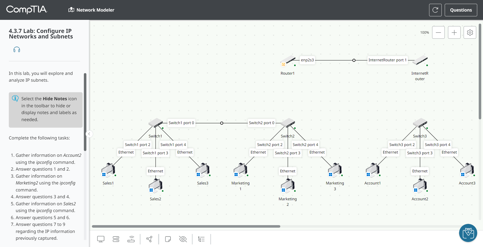
Above: A video of the network modeler in action, showing key functionality.